

アスクJANコード 4537694167918
特徴
![]()
TDP 250W対応
- ハイエンドCPUのオーバークロックにも対応する TDP250W対応設計!
VR&PWMファンクション コントローラー付属
- オーバークロッカーに人気のVR制御方式と 静音性を重視するユーザーに人気のPWM制御方式を切換可能なコントローラー付属
使用状況に合わせたセッティングが可能!
最新CPU Sandy Bridge-E対応!
- 最新CPU Sandy Bridge-E に採用された インテル最新プラットホーム LGA2011ソケットに対応
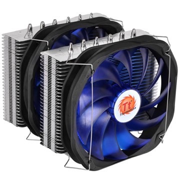
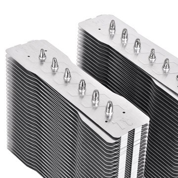
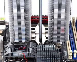
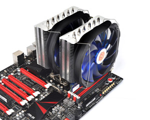
デュアル ヒートシンク & デュアルファン構造
- 冷却面積の増大とデュアルファンの風量を最大限に活かす デュアルヒートシンク構造を採用
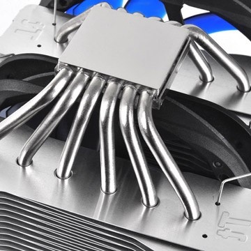
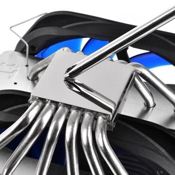
ヒートパイプx6 & ミラー フィニッシュ ベース
- ベースをニッケルコート&ミラー処理することにより CPUとの密着性をアップ!
φ6mmの銅製ヒートパイプ6本が 迅速な熱移動を実現
アルミニウム フィン x112
- フィン56枚の広大な冷却面積を誇る ヒートシンクをデュアル配置することにより トータル112枚の冷却フィンを搭載!
隣接するフィンに段差をもたせ、接触面を湾曲させた構造のフィンによりスムーズな気流導入とノイズの軽減のを実現
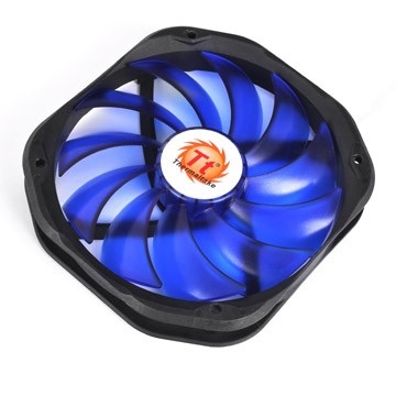
PWM対応 140mm 静音 ファン
- ブルーのブレードが目を引く 140mmの静音PWM制御ファンを採用
ユニバーサルCPUサポート
- Intel LGA2011/1155/1156/1366/775 およびAMD FM1/AM3/AMM2+/AM2に 対応するユニバーサルバックプレート&クリップ
プレミアム サーマル グリス付属
- 熱伝導効率の更なる追求! プレミアム サーマルグリス 付属
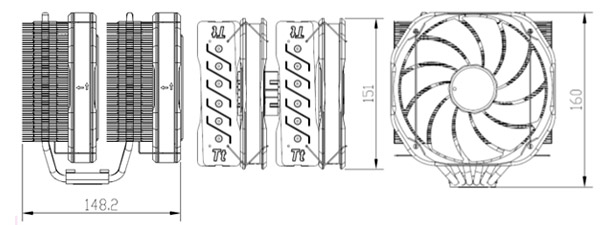
寸法
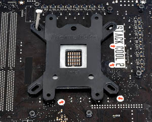
Intel Motherboard Installation
| Step 1 | Step 2 |
 |
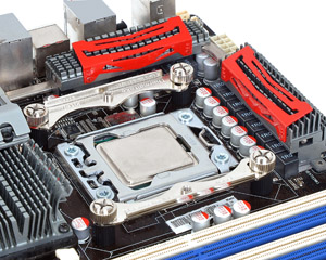 |
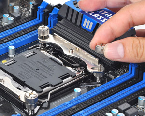
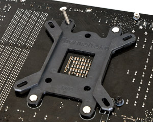
| Insert the four long screws through the back-plate into the four holes on the motherboard and secure them with the four plastic spacers evenly. | Put the two Intel mounting bars along with the four long screws and secure them with the four nuts. |
| Step 3 | Step 4 |
 |
 |
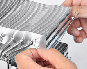
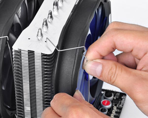
| For LGA2011: Screwing the LGA 2011 screw onto motherboard tightly and put the two Intel mounting bars on the LGA 2011 screws. Fasten the four nuts onto the mounting bars tightly. | Install the fan clips onto the heat-sink separately |
| Step 5 | Step 6 |
 |
 |
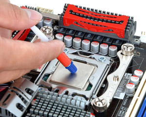
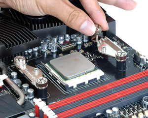
| Applying a thin layer of thermal grease onto the CPU. | Applying a thin layer of thermal grease onto the CPU. |
| Step 7 | Step 8 |
 |
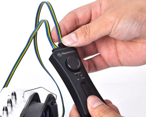 |
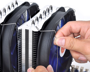
| Fix the two fans onto the heat-sink with fan clips separately. | Connect two fan cords to the controller close to the VR Knob. Link the power cord to the CPU FAN slot and the right slot of the controller. |
| Step 9 | |
 |
|
| Connect the 4-pin wire of controller to the motherboard’s CPU fan connector. Installation is done. |
AMD Motherboard Installation
| Step 1 | Step 2 |
 |
 |
| Insert the four long screws through the back-plate into the four holes on the motherboard and secure them with the four plastic spacers evenly. | Put the two AMD mounting bars along with the four long screws and secure them with the four nuts. |
| Step 3 | Step 4 |
 |
 |
| Install the fan clips onto the heat-sink separately. | Applying a thin layer of thermal grease onto the CPU. |
| Step 5 | Step 6 |
 |
 |
| Screw the heat-sink onto the motherboard with the mounting plate tightly. | Fix the two fans onto the heat-sink with fan clips separately. |
| Step 7 | Step 8 |
 |
 |
| Connect two fan cords to the controller close to the VR Knob. Link the power cord to the CPU FAN slot and the right slot of the controller. | Connect the 4-pin wire of controller to the motherboard’s CPU fan connector. Installation is done. |
| P/N | CLP0587 |
|---|---|
| Compatibility |
Intel LGA 2066/2011-3/2011/1366/1156/1155/1151/1150/775 AMD FM2/FM1/AM3+/AM3/AM2+/AM2 |
| 本体サイズ | 148.2(L) x 151(W) x 160(H) mm (2 Fans) |
| Heatpipe | 6mm x 6 PCS |
| 端子 | 4 Pin |
| 寸法 | 140(L) x 140(H) x 25(W) mm |
| ファンスピード | 1200 ~ 1800 RPM |
| Rated Voltage | 12 V |
| 定格電流 | 0.5 A |
| 入力電源 | 7.2 W |
| 最大風量 | 106.2 CFM |
| Static Pressure | 2.34 mmH2O |
| ノイズレベル | 38 dBA ~ 18dBA |
| Life time/Fan Life time | 100,000 Hours |
| Cooling Power |
250W |
| 重量 | 1,230g |
| Warranty | 10 Years |
User Manual
- ファイル名
- 概要
- サイズ
- Version
- Release Date
-
Frio Extreme Manual

- 2021-10-15
